Radio Frequency (RF) Wireless Microphone Guide
Jeremy Estes, September 2016 15 Sep 2016Contents 1 Introduction 2 Tech: Wireless microphone concepts, stock, transmitters and receivers Transmitters and receivers Performance Hall Stock Shure Wireless SM87A Microphone Antennas and the Mobile Receiver Unit Transmitter: Frequency Adjustment and lock Transmitter: Power Lock Transmitter: Internal Gain Adjustment Receiver: Frequency Adjustment Receiver: Internal Gain, Frequency and Volume Lock Finding New Frequencies 3 How to setup and use wireless microphones Patching Wireless microphones in the Performance Hall amp room Setting up and using a handheld wireless microphone Setting up and using Lavalier (Lav) Microphones Setting up and using a Countryman Headset 4 Troubleshooting My microphone(s) are cutting out on stage or in the house I am getting a lot of noise and scratching on my lav channels
List of Figures Figure 1. The Shure SM58 and lavalier microphones (left and top (transmitters)) and a receiver (bottom) Figure 2. Image of the first four (1-4) wireless receivers installed in the patchbay Figure 3. Image of the next four (5-8) mobile receivers Figure 4. Image of the SM87 wireless microphone Figure 5. In house perspective of the supposed locations of the two catwalk antennas Figure 6. Active directional vs. active omni-directional antennas Figure 7. Labeled image of a transmitter screen Figure 8. Internal gain parameters for both the handheld and lav pack Figure 9. Labeled image of the receiver display (lock icons not visible) Figure 10. Image of part of the patch bay in the Performance Hall amp room Figure 11. The proper way to use a handheld microphone Figure 12. Example of proper lavalier microphone placement Figure 13. A Countryman Headset
1 Introduction
Welcome to the RF wireless microphone guide. This guide is for either (a) new employees who are looking to learn how a wireless microphone works as well as how to set one up, or (b) any employee trying to troubleshoot a wireless microphone, transmitter, receiver, or all of the above. This guide will explain the basics behind Shure’s ULX series of RF (radio frequency) microphones, how to adjust and find frequencies on both the transmitter and receiver, how to lock and unlock frequency, volume, and power settings on the receiver and transmitter, the different types of wireless microphones we own in the hall, and how to set up and properly use those microphones in a variety of settings. In total we own 10 wireless ULXP4 receivers, each with its own handheld SM58 (or in two cases SM58A) and lavalier microphone. We also own two Countryman Headsets, which can be interchanged with the lavalier microphones as needed.
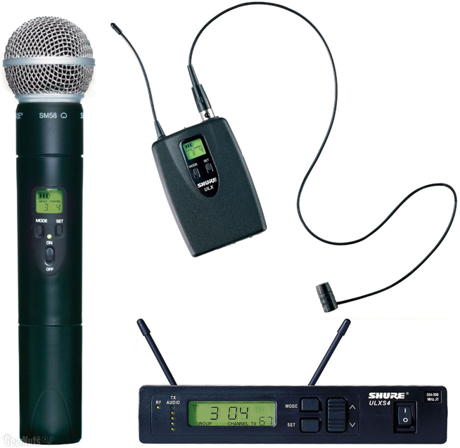 Figure 1. The Shure SM58 and lavalier microphones (left and top (transmitters)) and a receiver (bottom)
2 Tech: Wireless microphone concepts, stock, transmitters and receivers
Transmitters and receivers A wireless microphone consists of a transmitter and a receiver. The transmitter is oftentimes the microphone itself, or in the case of a lavalier microphone (top of Figure 1) it is the small black box that the microphone plugs into and is clipped onto to the performer. Therefore oftentimes when you hear the word ‘transmitter’ in the audio world one of the first things that should come to mind is simply a wireless microphone. Our wireless handheld SM58s are an example of microphones that double as transmitters. In this guide I will often use the term ‘transmitter’ to refer simply to a wireless microphone. Figure 1 displays the handheld wireless SM58 microphone (left in the image), a lavalier microphone and transmitter (top of the image), and a receiver for both (bottom of image). The transmitter takes the electrical signal generated from the diaphragm of the microphone and converts it to a light wave of a particular band of radio frequency, denoted by the combination of letters and numbers (group and channel) on the screen of both the transmitter and the corresponding receiver. The group and channel is set by the user. This RF signal is transmitted throughout the space and picked up by antennas connected to the receiver corresponding to the particular transmitter being used. The receiver takes the signal and converts it back into an electrical signal, to be sent to your mixer or elsewhere.
Performance Hall Stock As I mentioned in the introduction, we own ten total receivers. Four of these ten are installed in the amp room of the performance hall (labeled W1 - 4 for Wireless 1, Wireless 2, etc…).
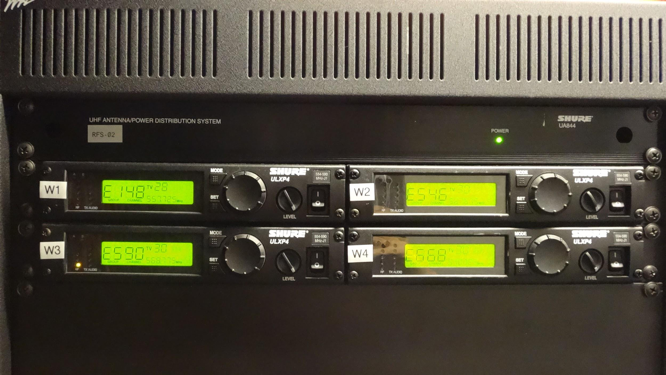 Figure 2. Image of the first four (1-4) wireless receivers installed in the patchbay
Another four are installed in a mobile rack unit that also lives in the back of the amp room (labeled W5 - 8).
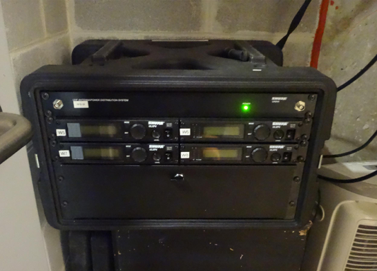 Figure 3. Image of the next four (5-8) mobile receivers
The other two are installed in the mobile rig. Each receiver has its own handheld SM58 and a lavalier microphone and transmitter. This means that if you are working in the hall, you can have a total of eight wireless microphones working simultaneously. These eight can be any combination of lavs and handheld wireless microphones, as long as at the end of the day no more than eight channels are in use at any one time. Therefore if someone managing a show asks how many wireless microphones they could potentially use at once on stage (this is a very common question), you should explain to them that there are eight wireless channels, so any combination of handhelds and lavs can be used as long as the total remains eight or under. If you are using eight lavs, then you cannot be using any handhelds and vice versa.
Shure Wireless SM87A Microphone In addition to the eight wireless handheld SM58 microphones that come with each receiver, we also have a wireless SM87A microphone that should always be set to the same group and channel as wireless unit 4. (I thought this was usually set to W1? Most likely it changes a lot but W1 matches the lack of tape on the mic)
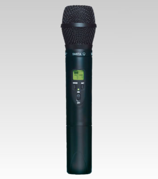 Figure 4. Image of the SM87 wireless microphone
The SM87 is a higher quality vocal dynamic mic with a different polar pattern from the more common SM58. It is better suited for professional vocalists who have extensive experience with microphones. As with any other wireless system, you cannot use both this microphone and wireless microphone 4 or lav 4 at the same time. Remember that the number of receivers is what determines the total possible number of wireless microphones that can be used simultaneously. A receiver can only ever have one corresponding transmitter at a time, even though we own multiple transmitters for each receiver. If you would like to learn more about the features of the SM87A, or of any of the microphones we own, please refer to our microphone user guide which can be found here: (insert link)
Antennas and the mobile receiver unit In the performance hall, we have two Shure active directional antennas installed in the catwalks directly above the front edge of the stage, positioned to optimize incoming signal from transmitters onstage. There is one directly above the downstage left corner, and one directly above the downstage right corner. These two antennas pick up signal from any of the eight wireless channels (transmitters) whose corresponding receivers live in the amp room. They are supposed to both point toward the center of the stage. If one or both get knocked out of place, this may cause interference or other issues with your microphones. Therefore if you are having trouble with microphones cutting out during sound check, either go onstage and try to check by looking up at the antennas to see whether or not they are aligned as necessary, or go up to the catwalks and check that way.
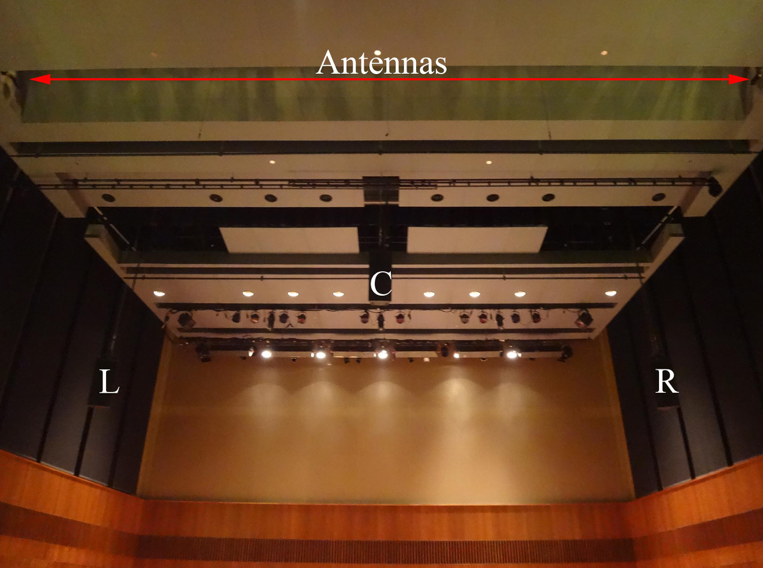 Figure 5. In house perspective of the locations of the two catwalk antennas
If the problems you are having are only with wireless microphones 5 through 8, (the ones whose receivers live in the mobile rack unit in the amp room (Figure 3)), then go into the amp room and find the mobile unit behind the patchbay next to the north facing door of the amp room. Two splits from the antennas in the catwalks come down and connect into the front of this mobile unit, providing the signal for these four channels. These look simply like two thick black cables that connect to the front top two corners of the unit via BNC connector. Check to make sure that both of these are plugged in. Note that you can also plug these in in the back of the unit, and so sometimes you will find them plugged in this way. Also note that due to the particular placement of these antennas in the catwalks combined with the fact that they are active directional as opposed to active omni-directional, you may experience cut outs and interference at front of house, so if you are testing a mic at the sound board and find that it is cutting out, don’t worry; it is probably just the fact that you are standing at front of house. Have someone take the mic and check it in other parts of the house and or on the stage to confirm whether or not this is the case.
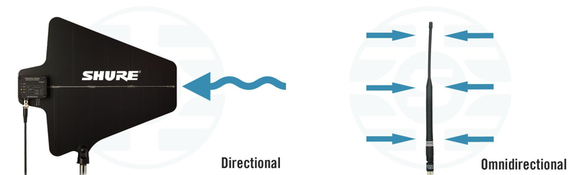 Figure 6. Active directional vs. active omni-directional antennas
This mobile unit also gets used in other spaces when more wireless microphones are needed with the mobile rig. When this happens the user has to disconnect these two thick black wires and replace them with the omnidirectional antennas that can be found inside the pullout drawer of the mobile unit itself. In addition to this, the outputs from the four receivers in this unit must also be disconnected from their respective XLR connections that connect them to the patchbay, so that the entire unit can be moved as necessary. These connections are usually just left on the floor behind the mobile unit. Many times people return the unit after using it somewhere else but forget to plug the hall antennas back in as well as these outputs of the receivers to the XLRs that go into the patchbay. If this happens then you will most certainly have problems if you try to use wireless channels 5 through 8 in the hall. If the antennas are disconnected, you should be easily able to discern the two thick black cables unplugged and hanging down from the ceiling in the space between the north door and the patchbay. If the outputs of the receivers are also not plugged in then you should just as easily be able to find the four disconnected XLRs laying on the floor behind the patchbay. They are labeled so that you know which output to plug into which patchbay XLR.
Transmitter: Frequency adjustment and lock As I mentioned briefly in the first part of this section, the transmitters and receivers both have screens containing information about battery power, frequency selection, and lock settings, among other things. What we need to worry about is the battery power and sometimes the frequency. The battery power is straightforward and requires no explanation. Before doors for a show are about to open, all wireless microphones being used should have fresh batteries. That means that the battery power indicator should be showing full power.
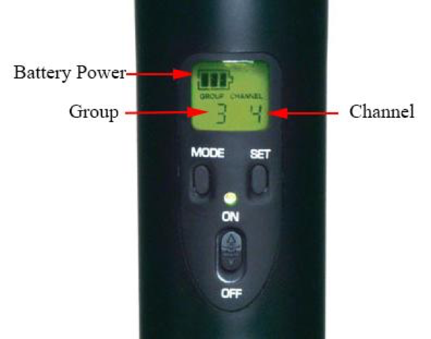 Figure 7. Labeled image of a transmitter screen
The frequency that the transmitter and receiver are operating at is denoted by what is called the group and channel on the digital screens on both the transmitter and the receiver. A transmitter is matched to a receiver by its group and channel. The group picks out a wide range of operational frequencies, and the channel picks out a more specific band of around 200 kHz, known as the operating range, within which the particular transmitter and receiver will communicate with each other. Contrary to popular belief, the group and channel do not pick out a particular frequency, but rather this band of frequencies. Auditory information is conveyed via frequency modulation, or FM, something you may know from radio, or TV. This means that the information is transferred by way of a wave of varying frequency, as opposed to a wave of varying amplitude, from which comes amplitude modulation, or AM. The term RF, or radio frequency, comes from the fact that this broadband of frequencies is more generally always contained within the much larger band of radio frequency light. Technology has not yet advanced enough to allow us to create cheap transmitters and receivers that can communicate via light of higher frequencies such as microwave or ultraviolet, therefore virtually all of today’s wireless technology–cell phones, wifi, radio, TV, etc…–communicate information between devices by way of frequency modulated radio wavelength light. (inb4 gravitational wave transmitters thx LIGO)
It is Performance Hall policy to change ONLY the group and channel of the transmitters to match that of the receivers. This is because the group and channel of the receivers was determined by a complex process of finding frequency bands that are not being overused in the general Chicago area, so as to prevent interference and optimize the functionality of these devices. It is more likely that someone changed a transmitter to match a different receiver, therefore we prefer if you change the transmitter back to its receiver, rather than changing another receiver. If you pull out a wireless microphone, turn it on, and notice that its group and channel do not match those of its corresponding receiver, then you should change the group and channel of the transmitter (microphone) to match that of the receiver. Note that any microphone and any receiver we own can work together, however for the sake of clarity and organization we have coupled microphones to receivers and labeled both in order to keep things neat and in order. Please help us maintain this by making sure the right transmitters and matched to their properly labeled receivers.
To change the group and channel of a transmitter (this goes for both handhelds and lavs) you must first check to see whether or not the frequency is locked on the transmitter. To do this simply hit the mode button while the microphone is on. If the frequency is locked, the mode and set buttons should have no effect, and so when you hit the mode button you should see a brief ‘Fr L’ message appear indicating the the frequency is locked. In order to unlock the transmitter, hold down the set button while the microphone is on. Turn the transmitter off, then, continuing to hold the set button, turn it back on. You should see a quick ‘Fr UL’ for frequency unlocked. Now that the ‘mode’ and ‘set’ buttons are active, you can use the former to toggle between the group and channel, and the latter to toggle between different groups and different channels. Thus if you needed to change both the group and channel of the transmitter, hit the mode button once to highlight the group, then hit the set button to change groups. Hit the set button until the desired group is showing, then simply hit the mode button again to switch to channel. Use the set button again to get to your desired channel (you can hold it down to sweep through a large number of channels if necessary). Once your desired channel is showing, simply hit the mode button again to go back to the home screen. ALWAYS lock the frequency again after you are done changing it. To do this, simply hold the set button while in the home screen (nothing highlighted. If you hold the set button while in group or channel mode you will simply start sweeping through either groups or channels, so make sure to hit the mode button until you are back at the home screen, with nothing highlighted). Turn off the transmitter while holding the set button. Then, continuing to hold the set button, turn the microphone back on. You should see ‘Fr L’ for Frequency Locked briefly appear on the screen, and the lock icon should again be active.
Transmitter: Power lock These ULX series transmitters also have the option to lock power, so that if anyone was using a microphone on stage and accidentally hit the power switch, nothing would happen. It is Hall Policy to use the sleeves we have in each microphone case for this purpose (only applicable for handhelds), however to make this guide comprehensive I will explain here how to power lock the transmitters if it ever became necessary. To do this, turn your microphone on and hold both the set and mode buttons down for four seconds. You should see ‘Po L’ for Power Lock briefly appear on the screen. To unlock the power, simply hold the set and mode buttons again for four seconds. You should see ‘Po UL’ for power unlock briefly appear. Again, it is not our policy to use this feature, but rather the sleeves we own for each microphone (every wireless handheld microphone should have both a sleeve and a stand clip in its case). To be extra cautious you could power lock the transmitter in addition to sleeving it, however you should never neglect to sleeve it and only power lock it.
Transmitter: Internal Gain adjustment Both transmitters and receivers have their own internal gain parameters which we prefer to leave at a particular semi-permanent level. On the transmitter, if you are using a handheld wireless microphone, the internal gain can be found just above the battery compartment in the bottom of the microphone (Right image of Figure 8). Unscrew the bottom capsule like you would do to change the battery and, holding the microphone with its screen facing you, find the small hole drilled just above the battery compartment. Inside this hole you should see some white plastic material carved into which is the shape of an arrow.
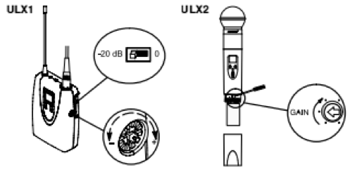 Figure 8. Internal gain parameters for both the handheld and lav pack
This arrow indicates the internal gain of the microphone. Maximum gain is at about one o’clock. We try to leave ours set at between 11 and 12 o’clock. If you need to change the internal gain for any reason, go into the Performance Hall stock and find the shelving unit labeled ‘Special Screwdrivers.’ There should be a very small, thin screwdriver with an asterisk shaped end that looks like it would fit into the internal gain hole in the microphone. Grab this screwdriver and use it to twist the arrow until it is pointing where you want it to. For consistency’s sake, please try to leave all handheld transmitters at the same internal gain, between 11 and 12 o’clock.
If you are using a lav pack and microphone, the internal gain can be found along the right edge of the lav pack (left image in Figure 8). It looks like a plastic dial. Use your fingers to twist it clockwise to increase the gain, and counterclockwise to decrease the gain. We typically leave these at maximum gain.
Receiver: Frequency adjustment (are you worried about including this in a general use guide? I don’t want to encourage people to approach the receivers) There is only one time when it should become necessary to change the group and channel of a receiver (otherwise you should only be changing that of the transmitter to match the receiver), and that is when it has been generally agreed that a particular frequency band is experiencing interference and or is picking up signal other than that coming from its corresponding transmitter due to increased traffic on that frequency band. If this is the case, then the first step is to find a new frequency band (group and channel) that is relatively unused in your area. The last part of this section details how to do this. This part is dedicated to explaining how to change the group and channel of a receiver once you have found a robust frequency band.
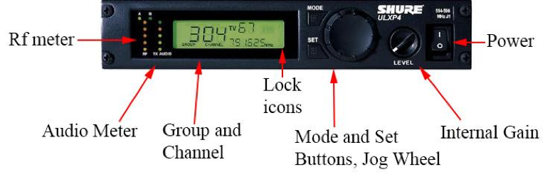 Figure 9. Labeled image of the receiver display (lock icons not visible)
The receivers, like the transmitters, have a frequency lock. This lock should be active on every receiver in the Performance Hall stock. If it is you should see a little lock icon in the position indicated in Figure 9 (the receiver in the image is unlocked). To unlock the frequency controls on a receiver, hold the ‘set’ button, and turn the jog wheel a quarter turn left, a quarter turn right, and a quarter turn left, then release the set button. If you did it right you should see the frequency lock icon disappear on the receiver’s screen (as imaged above in Figure 9) and you should be free to change the group and channel as necessary. To change the group, hit the mode button twice, or until the ‘Group’ icon is highlighted, then use the jog wheel to get to the group you want. Hit the ‘Set’ button to set the group as such. Hit the ‘Mode’ button one more time to highlight ‘Channel’ and use the jog wheel again to reach the necessary channel. Hit the set button again to set the channel.
Receiver: Internal Gain, Frequency and Volume lock The knob to the right of the jog wheel on the ULX receivers acts as the internal gain for the receiver. These should always be left at maximum, which is at about five o’clock. The receivers as we know have a frequency lock, however they also have a volume or internal gain lock. The procedure for locking either or both of these is the same. On the receiver, first hit the ‘set’ and ‘mode’ buttons simultaneously, then hit the mode button twice. This should highlight your two possible lock icons, for frequency and gain. Use the jog wheel to toggle between frequency lock, power lock, or both, and then hit the ‘set’ button to confirm your choice. Please remember to lock both volume and frequency after successfully changing the group and channel on a wireless receiver.
Finding new frequencies There are a variety of ways one can go about finding unused frequencies for the ULX receivers. I will only cover the two easiest ways, provided by Shure themselves. The first and most straightforward is Shure’s frequency finder:
https://www.shure.com/americas/support/tools/wireless-frequency-finder
Following the link above will take you to a website that asks for your zipcode and the wireless system series you are looking for frequencies for, which in our case is the ULX-P series. You can ignore the fact that it says (Discontinued) next to this selection; the finder still works. Once you enter this information the website will list the potential available groups, and expanding any of those groups will allow you to see which channels are open.
The other, possibly quicker way to do this is to use the receiver itself, which has a built in feature that searches for open groups and channels in the area. Scanning for groups is useful for finding the group with the most open channels. To do this first hit the mode and set buttons simultaneously, then use the jog wheel to scroll until you see the words ‘SCAN GROUP’ appear. Hit the set button to start the scan. The receiver will show the group with the most open channels, as well as the number of open channels (between the battery power and channel icons) in that group, denoted by the words ‘OPEn CH’ directly beneath that number. To scan a group for an open channel, hit the mode button once, or as many times as necessary until you see the words ‘SCAN CHANNEL’ highlighted on the screen. Turn the jog wheel a quarter turn clockwise to start the scan, and hit the set button to set the resulting channel as your new channel. Note that the receiver must be frequency unlocked in order to do this.
3 How to setup and use wireless microphones
Patching wireless microphones in the Performance Hall amp room Probably one of the most common everyday tasks that must be completed in a regular shift in the Performance Hall is patching one or multiple wireless microphones in the patch bay in order to send the signal that comes from the microphone and receiver up to the Venue (soundboard) at Front of House (FOH). Patching refers to the general idea of taking signal from one source and manually sending it to another source via a cable or wire. Below is an image of part of the patch bay in the amp room:
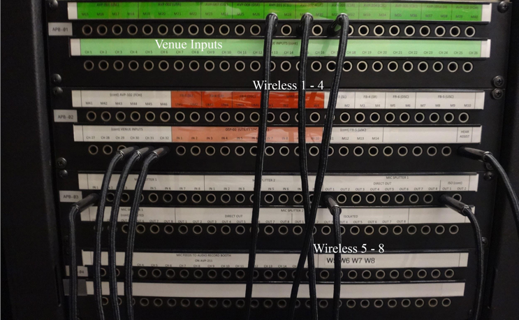 Figure 10. Image of part of the patch bay in the Performance Hall amp room
Each row of quarter inch inputs is color coded to tell you whether signal is supposed to come FROM or go TO those inputs. For example, the green row labeled ‘Venue Inputs’ are inputs that signal is supposed to be sent TO, while any red rows represent inputs where signal is supposed to come FROM.
In order to send signal from any of wireless 1 - 4, you must find the red row labeled ‘Wireless’, take a quarter inch to quarter inch cable (either green or red) from the rack of hanging cables on the north wall of the amp room, and plug in one end to your desired Wireless output, and the other end into your desired Venue input (see Figure 10 for visual locations of wireless patches). Thus, if I was using W1 on Venue input 2 I could say that I patched W1 to channel 2 on the Venue. Similarly, when you are patching anything else, the key is to think about where your signal is coming from, and where you want it to go once it is in the patchbay. This will help you find your way around when you are still getting use to the often intimidating amp room. Note that if the Mobile Wireless rack unit with Wireless channels 5 - 8 is plugged in correctly as I described in Section 2 to the patchbay, you can find those inputs a few rows below Wireless patches 1 - 4. They are labeled 5 - 8 with large numbers and patch the same exact way as I just described for 1 - 4.
Setting up and using a handheld wireless microphone Once you have successfully patched your wireless microphone and confirmed on the Venue that you are getting signal to the right input channel, you should do a sound check with whoever it is will be using the microphone on stage. This can be more difficult then it may sound, so do not be surprised when you end up having to work with someone who talks into the wrong end of the microphone and yells at you because it doesn’t seem to be working. If it seems that your speaker is someone who is not an experienced microphone user, then there are a few things you should warn and or teach them about during soundcheck. The first is simply how to hold and properly use a microphone. The easiest way to do this is to go down on stage with the microphone and show them how to do it yourself. If you yourself are unsure about how to properly hold it, simply refer to the image below.
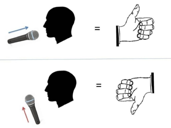 Figure 11. The proper way to use a handheld microphone
The main points are pointing it directly at your mouth, and holding it about two inches away in that position. Before you return to your board you should also warn them about the sleeve that you will be placing on the microphone before the show. This consists of explaining to them that the microphone will be on and ready to go when they need it to be, and not to worry when they realize they can’t access any of the buttons on the microphone due to the sleeve. Try to explain to them as best you can that you have total control over the microphone when you are at the board, and that they need not worry about anything related to tech.
Setting up and using Lavalier (Lav) microphones Lavalier microphones are some of the most finicky microphones we have in our stock. They are small microphones that clip on to the speaker’s clothing just below the neck to pick up vocal audio for talks, conferences or other more speaker oriented events. You have probably seen them on news reporters or lecturers before. The microphone has a wire that connects to what we call the lav pack (the transmitter). This lav pack has a belt clip to clip on to belts or other more sturdy items of clothing.
As I mentioned earlier, every wireless receiver has both a handheld and a lavalier microphone corresponding to it, however you can only ever use one or the other at a time. The lav microphones are very sensitive, and so set up and placement plays an absolutely critical role in how well they will serve their purpose during your show. You or another tech or someone from our staff should always be the ones outfitting speakers or performers with their lav mics. Before placing the lav on the speaker, test it yourself by plugging the microphone into the transmitter and flipping the switch on the top of the transmitter to turn it on. After you have confirmed that it is working, find the person who is supposed to use the lav during the show and do your best to explain to them as clearly and concisely as possible that lav mics are very sensitive to sudden movements and in general will pick up any and all noise around them. Make sure they know not to touch the lav after you place it. If you are working with a performer who is going to be doing anything other than standing absolutely still or sitting down for the duration of their time on stage, then you should strongly suggest that they use a Countryman headset instead of the lav (see the next part of this section).
When placing the lav you should assume the worst about the person you are outfitting. That is to say, you should assume that they are going to forget everything you just told them about how sensitive the mic is to movement, and that they are probably going to walk around, move and or jerk their head, and even make sudden movements with their body. Bearing these things in mind, clip the microphone onto clothing preferably no more than a few inches from their neck, in a place that seems most stable when it comes to movement. In other words, try not to clip the lav to any loose clothing. In fact, if you are testing a mic on a performer whose event is not within the next few hours you ought to tell them that any loose clothing around the neck or chest, like scarves or loose jackets, should be avoided as much as possible. Even the smallest touch will be heard as a loud boom in the hall during the performance. Refer to the figure below for an example of proper lav mic placement:
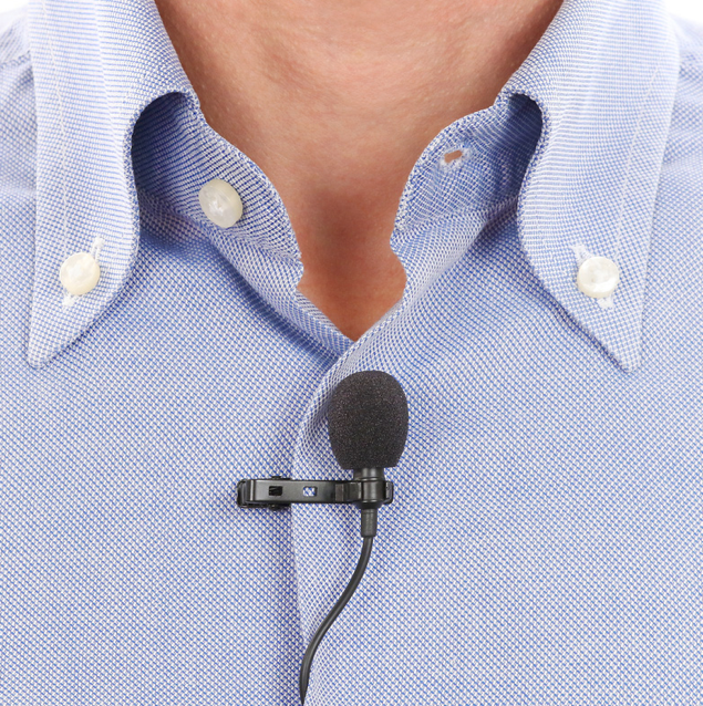 Figure 12. Example of proper lavalier microphone placement
This image is a fairly good representation of proper lav placement, however there is one major problem with it. It looks as though the seam of the shirt that the lav is clipped onto is going to rub against the side and top of the microphone. This is definitely something you should try and avoid. The microphone should always be pointing toward the mouth of the speaker, however it should not be obstructed by clothing like this, especially if that clothing looks as if it may touch or bump into the microphone. If the microphone in the image above was clipped slightly lower on the shirt, this problem might be solved.
As for clipping the lav pack or transmitter, try to find a belt or some sturdier article of clothing on the backside of the person to clip it onto. Sometimes if you are working with someone wearing a dress and a bra, clipping it onto the bra clip on their back can work well.The lav pack simply needs to be hidden as best as possible in a place that is not uncomfortable for the speaker. Pockets work fine for this purpose assuming there is virtually no chance of the pack falling out during the performance, HOWEVER, make sure to warn the person that they cannot place the lav pack too near a cell phone or other wireless device due to interference effects. Too near means in the same pocket as. You should also place the lav pack based on how it will best hide the wire coming from the microphone. If you need to tell the person that they need to feed the wire through certain articles of clothing, do not be afraid to do so. Kindly suggest to them that it will help their aesthetic if they don’t have a distracting wire dangling around in front of them during their performance. This usually convinces them to do something about the cable. Before the show begins and if you have time, have your stage manager check to make sure the pack is turned on and the lav is still placed properly.
Last but not least, if you are using many lavs at once on stage, kindly tell the performers to try and remain as far apart as they can, as we have found that putting many operating lavs into a small area causes interference effects in some of the mics.
Setting up and using a Countryman headset A countryman headset is a high quality and discreet microphone that is placed by way of a thin headset next to the mouth of the user. It is usually of nude color, and is designed for events which require a very clean and professional appearance while maintaining high fidelity audio signal.
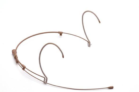 Figure 13. A Countryman Headset
We own two of these Countryman in our stock. They are used by replacing a lav microphone with the headset. It plugs into a lav pack in the same way that a typical lav does. The headset ear fittings rest over the ears of the user. The headset in the image is rightside up. It can be adjusted for the size of the head by gently pushing or pulling either of the extended ear fittings. The microphone should be placed preferably about an inch away from the corner of the mouth of the user. It should NOT be touching the check but rather a few centimeters away and can be adjusted to fulfill these requirements. The same guide lines that apply to lavs also apply to these, in terms of keeping the mic away from anything that could bump or rub into it (ie: the face of the user).
Though these microphones are much higher quality than the lavs, they are not without their limits either. There are a few critical things that come into play and that you should be aware of when using these mics. Firstly, they are just about as bad at dealing with bumps or sudden movement as any other mic is. It is their placement on the user that allows them to function better during situations in which the performer is moving around, thus it is critical that they are placed properly. Again, these mics should be placed by employees only, NOT the person who is going to be using them. That being said, make sure to tell the performer very clearly to refrain as best they can from adjusting the mic after you have placed it. Adjust them according to the head they are being placed on and then gently place the ear fittings over the person’s ears. Make sure the ear fittings are snug around the ears of the user, but not uncomfortable. If you are dealing with someone who has long hair, kindly suggest to them that they should pull their hair back if they do not want any annoying interference with the microphone. In addition to this be sure to caution strongly against the wearing of scarves and large/loose earrings and other jewelry that might interfere with the microphone. Once the microphone is placed, do a thorough sound check, having the performer walk around, shake his or her head, and do anything that they might think they will do during their performance that involves movement of any kind. This will test how well you have placed the microphone, as well as prepare you for what is to come during the show.
4 Troubleshooting
My microphone(s) are cutting out on stage or in the house If one or more of your wireless microphones are cutting out in the house or on stage, the first thing you should do is try to identify which mics are cutting out. If you find that only wireless mics 5 - 8 are having problems, it is most likely an antenna problem; namely, someone probably forget to plug one of the two antennas back into the mobile unit in the patchbay. You should also check to make sure that these four receivers are turned on, as they often get turned off after being used in a different location. If this is not the problem, or if you are also having trouble with wireless mics 1 - 4, first make sure you are not trying to run multiple transmitters on a single receiver. That is to say, make sure you are not trying to use both W1 and LAV1 at the same time, or W87A and W4, to give another example. Once you have confirmed that you only have one transmitter to every receiver being used, go to the receivers themselves and look at the RF indicator (Figure 9). The RF meter displays the strength of signal coming from the transmitter. If you are sure that all antennas are plugged in and working correctly, but your RF meter is only halfway or less lit up, then you are most likely experiencing interference from other sources around Chicago that are using the same group and channel. This could be a strong indication of needing to find a new frequency of transmission for the receiver. If you are in a desperate situation before a show is about to start, and you find that one or more of your receivers has less than maximum signal strength according to the RF indicator, then I would recommend using either of the two methods I outlined in the last section for finding new frequencies fast. Otherwise report the problem to a supervisor so that we can more thoroughly investigate the situation. If you end up changing the frequency, make sure that you also change the frequency of the transmitter to match up, and that you tell a supervisor about the change that you made.
Lastly, if you are using lavs and getting interference, in addition to the things aforementioned, your speaker may have placed his lav pack near his cellphone on his body, and or if there are many lavs at once placed on stage and very near each other, this may cause interference as well. These are things that you should simply warn performers about before the start of the show. If this is happening during the show, contact your stage manager and tell them to inform the performers as soon as they come off stage.
I am getting a lot of noise and scratching on my lav channels This is almost certainly due to poor placement of the lav on loose clothing, or its proximity to loose clothing combined with movement by the performer or speaker. This is why making sure that the performers are aware of the sensitivity of the mic to things like this is very important to get across before the show. A lot of times performers will be very reluctant to change their state of dress before a show, and you should only kindly suggest to them the option, however it is important to warn performers before the day of the show if possible so they can plan their dress accordingly to avoid problems like this. it is also not uncommon for performers to mess with the placement of the lav before the show, in which case having your stage manager go and make sure all of the lavs in use are placed correctly before they are supposed to come on stage cannot hurt you.
If you find yourself in the middle of show getting problems like this, the best you can do is to ramp up the high pass filter on whichever lav channels you are having problems with as much as you can while detracting as little as possible from the voice of the performer. This will help take care of things bumping into the microphone. In addition to this you can put a high ratio (5 or 6:1) compressor on the channel as well to help take care of the high end of these bumps that doesn’t disappear with the high pass filter. Other than this you can really only hope that the performer hears him or herself and realizes that his or her movements or loose clothing are causing the problem. If there is an intermission, or the performers in question go off stage for a while you can tell your stage manager to go and try to fix the lav to get rid of the noise. This is about the best you can do in this situation.