Mobile Rig User Guide
Jeremy Estes, July 2016 08 Sep 2016Contents
- Introduction
- Quick Start Guide: Cafe
- Quick Start Guide: Penthouse (901)
- The Mixing Console
- The Rack
1. Introduction
Welcome to the Mobile Rig User Guide. This guide is for employees of any level of knowledge. Practically however, if you are reading this then you are probably either (a): a new hire who is desperately attempting to get signal to your wireless microphone five minutes before doors, in which case I will immediately refer you to the quick start section of this guide; or (b): a more experienced employee seeking to take advantage of the many nuances and benefits the Mobile Rig has to offer its users. It will cover in detail every piece of hardware in the rig, in addition to the different loudspeakers that tend to accompany it. Please refer to the table of contents above in order to find the specific topic which you are looking to understand.
2. Quick Start Guide: Cafe
1. Powering up the rig
- The mobile rig and everything in it is powered by a single switch on the front top right of the rack. It is labeled ’RACK POWER.’ Before flipping this switch, make sure all of the covers (front, back and top) have been removed and put away, and find the Powercon to Edison cable that should be nicely coiled in the back of the rig. Note that the front and back covers of the rig double as tables, with a single pull out leg inside the cover. Pull this leg out fully and fit the metal hooks on one end of the cover into the fittings on the right side of the mobile rig to form the table.
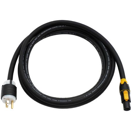 Figure 1: An Edison to Powercon Cable
Plug the Powercon end of this cable into the input labeled POWER at the back of the rig at the very bottom in the in-out (I/O) panel (Figure 2) by plugging it in and twisting it a quarter turn clockwise to lock it in place. Take the Edison end of the cable to the nearest outlet and plug it in. Now flip the power switch on the front of the rig. You should now have power!
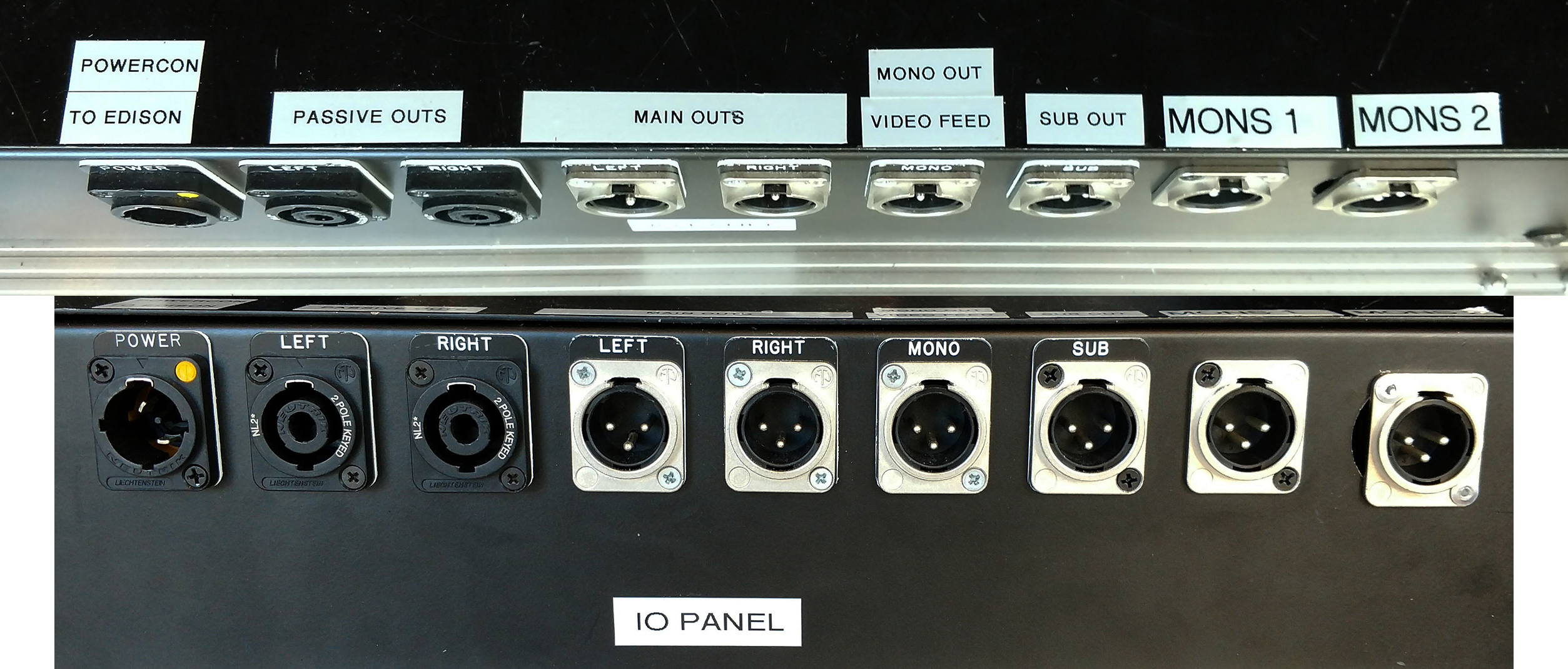 Figure 2: The I/O Panel of the Mobile Rig. Located on the bottom of the back of the rig.
2. Setting up and cabling speakers (EVs)
- If you are in the cafe, then you will need to set up your own mains. The term mains often refers to the two speakers–Left and Right–that point toward the audience and act as the main source of signal amplification. For this purpose we have our two EV TX1122 loudspeakers and a JBL EON 618s subwoofer.
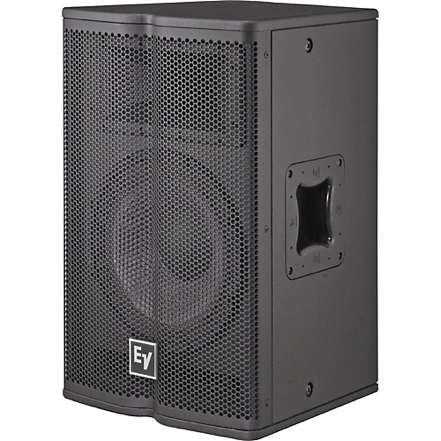 Figure 3: The EV TX1122 loudspeaker used for our mains with the mobile rig
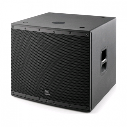 Figure 4: Our JBL EON 618s Subwoofer
If the event you are working is simply a lecture or speech, then you do not need to bring the sub, since in theory it ought only to amplify auditory information below the 100 ish Hz range. If your event contains live music with a drummer, dj, or general audio playback, then bringing and setting up the JBL sub would be much preferred. There is an output in the I/O panel of the rig labeled ’SUB’ for this purpose. Part 4 of this section details how to set it up. Assuming the event you are working is a simple lecture or speech however you will need to bring the two EV mains and their speaker stands with you to the Cafe. These two speakers can also be referred to as the PA or public address system. Make sure to set your PA up IN FRONT of the ”stage” if possible. In other words, try to set up the speakers so that the performer and more importantly his or her microphone are behind the imaginary line you could draw between the fronts of the two speakers. This is for the purpose of preventing feedback.
Once you decide on placement for your mains, take your speaker stands and loosen ONLY the bottom section that allows the legs to spread out. Do not touch the top sections, which are pressurized and can cause serious harm to someone who loosens them without a speaker already on the stand. Place the stands and retighten their lower sections. Pick up a speaker and place it on the top of the stand so that the top part of the stand goes inside the hole in the bottom of the speaker. Position the speakers by spinning them as needed. The main goal of speaker placement is relatively simple: even coverage over every point in the house, where the house is the area in which the audience is found. This becomes much more complicated then it may sound, however for our purposes just focus on pointing the speakers such that it seems in general that they cover as much of the audience as possible. In the cafe this can become difficult when the audience begins to overflow into the hallway that separates the kitchen from the general seating area and ’stage,’ however just do your best and don’t be afraid to refocus one of the speakers so that it points more in that direction. Your PA does not have to be set up in a symmetric configuration, though acoustically symmetry is usually preferable.
If you are a real stickler for speaker placement and want to make sure that you have done the best job possible when positioning your speakers, you can look up what is commonly called the beam width, or simply horizontal and vertical coverage of the speakers you are using. The beam width refers to the maximum angle which sound can cover coming out of the speaker. The horizontal coverage of our TX1122s is 90 degrees, while the vertical coverage is 50 degrees. When you place your speaker, stand in front of it and hold your arms out trying to make a rough estimate of the horizontal coverage of the speaker, this will give you a very rough idea of the area of coverage based on how you have placed the speaker. Typically you will not need to worry about the vertical coverage. If you did not touch the top knob on the speaker stands and simply left them as short as they can be then you will be good to go there. One last thing to remember when placing speakers is that in general you do not want any two main speaker paths to be crossing within the space you are working. That is to say that if you drew a line coming out of the front of each speaker and they intersected as some point in the house, then you want to reposition the speakers such that these imaginary lines are not overlapping. Refer to Figure 5 below for a visualization of this idea.
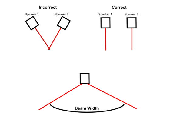 Figure 5: Visualization of proper speaker placement (top) and a top down view of the beam width or horizontal coverage of a speaker (bottom).
Once you have properly placed your speakers, find the two 50’ Speakon cables that live in the back of the rig along with the power cable and other various cables. The ends of these cables are blue and gray and look just like the end of the Powercon cable.
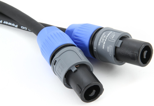 Figure 6: Speakon cable, also known as NL2 cable. (Note that this cable should not be confused with that which can be found in the amp room. They are NOT the same and the amp room cables should not leave there)
Plug these into the Speakon outputs labeled LEFT and RIGHT or PASSIVE OUTS in the I/O panel (Figure 2) right by the power input. The Speakon cables plug in the same way that the Powercon does. Take the other ends of each of the cables and plug each one into its respective speaker. It does not matter which of the two inputs on the back of the speaker you plug into. You are now ready to send signal to the speakers.
3. Getting signal to your mains
- Once your speakers are placed and plugged in, return to the rig and turn your three master faders up to unity, or 0 dB. There is one for Left (L), Center (M), and Right (R) respectively. These faders are found on the bottom right corner of the mixing console. Find the pullout drawer on the front bottom of the rig and take out one or both of the Shure SM58A Wireless Microphones. These microphones should be semi-permanently patched to channels 15 and 16 of the MixWizard and ready to go at all times. Turn on the microphone by flipping its switch. If it is dead you will need to unscrew the bottom cap and put a fresh 9 volt battery in, either from the pullout drawer or the Performance Hall stock.
Once the microphone is turned on, move your line of sight up from the pullout drawer to the two rack mounted wireless microphone receivers (Section 14 Figure 23). Tap or scratch the dome of the microphone while looking at the receiver; you should see some lights on the left side of the receiver respond to your touch. If you do not see anything and the receivers do not seem to be receiving signal from the microphones, check to see that the combination of numbers and letters on the little screen of the microphone match those on the receiver. If they do not, then you will need to refer to the Shure ULXP4 section (14) of this guide to change the frequencies (please note that if you need to do this, make sure to change the frequency of the microphone and NOT that of the receiver).
If you do see the lights on the receiver respond then move up to the mixing console on the top of the rig. The two input channels labeled W1 and W2 respectively can be found just to the left of the master faders. These are your two semi-permanent wireless microphone channels. Find the W1 channel fader, and hit both the mute button (to unmute if the channel is muted) and the circular gray button just above the fader labeled PFL (Pre-fade Listen). This will display the incoming signal from that channel on the meter just above the master faders. You can look at this meter to determine whether or not your channel is getting signal before you turn up your channel fader. Tap your microphone again to see if you are getting signal on the channel; the meter should respond to your touch. If it does, slowly turn up the W1 fader as you talk into the mic. If you hear yourself coming out of the speakers, then you did everything right! Now simply continue talking into the mic and adjust the gain knob at the very top of the input channel strip until your mic is at an agreeable level (optimally the signal on your master meter should be reaching just up to 0 dB, where the lights turn from green to yellow).
If you need a second wireless microphone, repeat the process with W2. If you need a wired mic, grab the mic and some XLR from the Performance Hall stock, or alternatively you can check these out from the Logan Media Center, and plug into whatever mic channel you would like on the back of the mixing console. Then repeat the steps above to check your mic (unmute, PFL).
4. Using the Snake and Setting up Monitors/Subs
- The Audio Snake: To make the cabling process from microphones and or monitors on stage to your mixer easier we have provided an audio snake that lives in the back of the mobile rig. An audio snake is simply a thick cable that is made up of many individual XLR and or quarter inch cables.
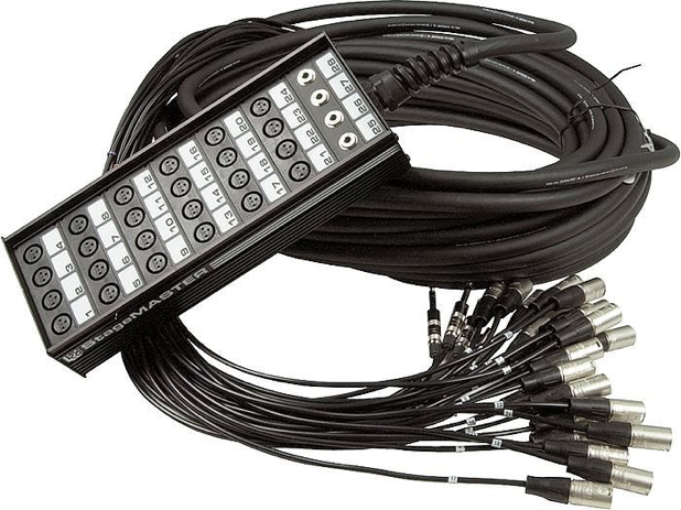 Figure 7: Image of an audio snake
- Monitors: There are a lot of shows both in the penthouse and the cafe which involve live musicians. If this is the case then you most likely will need to set up monitors, which are loudspeakers that point toward the performers so that they can hear themselves and other members in the band. The two JBL PRX612M loudspeakers which live in instrument storage serve this purpose for the mobile rig.
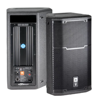 Figure 8: The JBL PRX612M which we use as a monitor with the mobile rig
There are two ways to set one of these up. If you look at the AUX send outputs on the back of the MixWizard (Figure 11) you should notice that there are two cables plugged into AUX 1 and 2 labeled MONS 1 and 2 respectively. These cables go to the DBX 215 units correspondingly labeled MONS 1 and 2 on the front of the rig. These are called graphic equalizers and are simply extra EQs for monitor processing. For details on how to set up a monitor through one of these two units, refer to section 13 of this guide.
The classic and straightforward way to set one of these up which bypasses the GEQs and uses instead any of AUX three through six requires one XLR male to quarter inch TRS cable and one Edison to IEC power cable. Usually the latter of these two cables lives with the speakers in instrument storage, squished beneath the handle on the side of the speaker. If not, you will have to grab one from the shelving unit backstage. The male XLR to quarter inch TRS cable can be found in Janice. These cables are fairly short, so grab some extra XLR and an extension cord considering how much additional length will be needed.
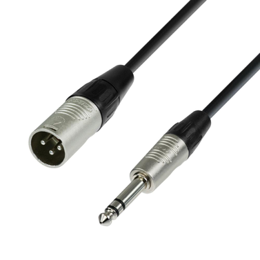 Figure 9: Male XLR to quarter inch TRS cable
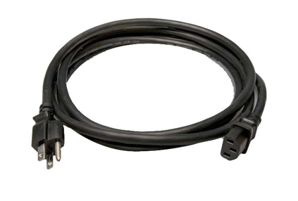 Figure 10: Edison to IEC cable
Place the monitor by getting it as close to the musician as possible without cramping his or her space. The speaker typically sits pointing up toward the musician, but it can be turned on its side, propped up with a roll of gaff tape, or placed on a stage cube depending on the height needed. Plug the IEC into the back of the speaker and the Edison into the nearest outlet or power strip. Turn the internal gain knob on the back of the speaker about half way up to start, make sure the monitor/main EQ button is set to monitor, and the set the input button to line level. Then plug an XLR into the input of the speaker, and cable back to your mixer or snake in a neat fashion (traveling in 90 degree angles and against the walls where possible).
Plug the quarter inch TRS end of your cable into AUX 3 on the back of the mixing console, or alternatively any of the other available AUXes if that one is already in use. If you are using the snake then find the quarter inch TRS male head corresponding to whichever input on the snake you plugged your monitor into and plug this end into the AUX. These AUX outputs can be found in the middle of the back of the mixing console, below 11 the mic/line inputs (Figure 11). Return to the monitor and flip the power switch on the back panel on. Now go to your master channel side of the mixing console (the right side), and find your master AUX knobs. If you are having trouble finding any of these things on the mix console please refer to Figure 12. If your monitor is plugged into AUX 3, turn the master AUX 3 knob up to unity (0 dB) and trace your finger directly to the left until you hit the AUX 3 knob corresponding to the channel that your mic is on. This knob will send an amount of the incoming signal proportional to the amount you turn the knob to whatever is plugged into the AUX 3 output on the back of the board, which in this case is our monitor. Before we do this, however, three knobs below this AUX 1 knob you will find a small, gray, square button labeled ’pre/post’ fader. Set this to pre-fader. This means that a split of the signal coming into that channel will be sent to the AUX BEFORE it reaches your fader. Therefore even when your fader is all the way down, signal can still be sent to the monitor, unless the channel is muted, in which case you will not get any signal out of the mains or the monitor from that particular input channel. Now talk into your mic and slowly turn up the AUX 3 knob on your mic’s channel. You should start to hear yourself in the monitor. If you do not, make sure the gain knob on the back of the speaker itself is turned up, check that your cables are properly plugged in, make sure the master aux knob is turned up and make sure your mic channel is unmuted and set to pre-fader. Again for details and locations of particular parameters on the mix console refer to Figure 12.
- Subs: Our EON 618s subwoofer (Figure 4) is also made by JBL and has a back panel very similar to that of the monitors from above. Plug an IEC to Edison into the sub and then into a wall outlet, plug an XLR into the ’SUB’ output on the I/O panel of the mobile rig (Figure 2) and into either of the two inputs on the sub, turn the internal gain knob on the sub up about halfway or so, and flip on the power switch on the back panel. You shouldn’t need to mess with any of the other buttons or parameters on the back panel, unless you need to turn off the LED on the front of the speaker, in which case you can hit the button in the upper righthand corner of the back panel labeled ’Front LED.’ Other than this, the setup is as easy as that. The signal going to the sub comes from the Left/Mono out of the DBX DriveRack PA+, so make sure you have both your left and right channels turned up when playing back stereo audio.
3. Quick Start Guide: Penthouse (901)
1. Powering up and getting signal to the mains
- In the penthouse the mobile rig is almost always placed in the northwest corner of the room. Assuming this is the case, we will use the wall AVP on the north wall for power and signal flow. For specifics on powering up the rig refer to part 1 of section 2. Otherwise, plug your power cable into the north wall AVP. The penthouse has two main speakers built into the east wall, therefore you do not need to bring up any speakers with you unless you need monitors. To get signal to the built in mains, take two XLRs (there should be two fifty footers which live in the back of the rig) and plug them into the XLR outputs labeled LEFT and RIGHT on the I/O panel on the back and bottom of the rig (Figure 2). Cable these behind the curtains on the north wall over to the AVP panel where you plugged your power in. Plug the ”LEFT” XLR into TL1 (Tieline 1) and the ”RIGHT” into TL2 (Tieline 2). The patches from there to the mains are usually left untouched, however if you test a mic and find that you are getting signal out of your console and into the wall but not out of the mains, then refer to the Penthouse User Guide, which details the house patching and how to troubleshoot anything that might come up.
4. The Mixing Console:
The mixing console in the mobile rig is an Allen and Heath MixWizard3 16:2. It has 16 mic/line inputs with inserts and direct outs, 2 stereo returns (ST1 and ST2), Left/Right/Center outputs with inserts, an extra AB out which we use for recording, and 6 Auxiliary outputs, typically used for monitors.
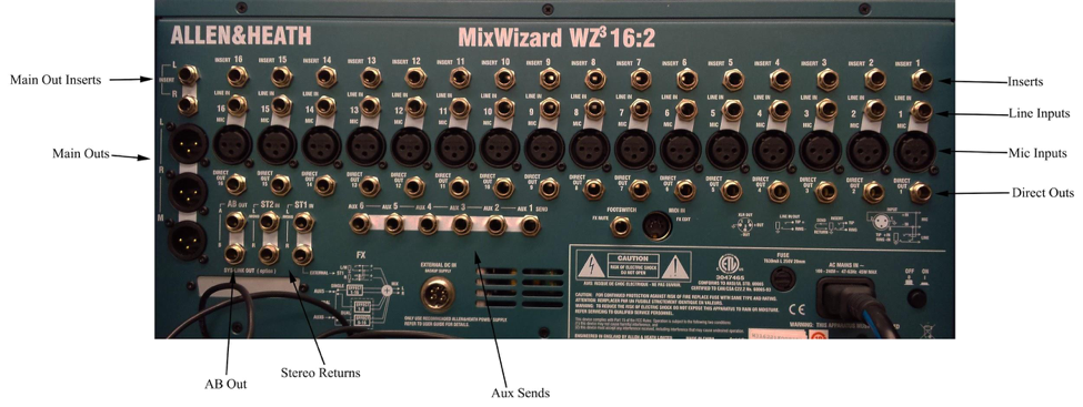 Figure 11: A labeled image of the back of the MixWizard Console
Channel Strip:
Each input channel strip has from top to bottom: a 48 volts phantom power button, a -20 dB pad button, a gain knob, an 80 Hz high pass filter button, a four node semi-parametric EQ, AUX send knobs for AUX sends 1 through 4, a pre/post fader button, AUX send knobs for AUX sends 5 and 6, a pan knob, a mute button, a pre-fade listen button (PFL), and finally the channel fader. The EQ is equipped with high and low shelves at 80 Hz and 12k Hz respectively and high mid and low mid bells (1.8 Q) which together can be swept along the full frequency range (30 Hz to 15k Hz). All of these parameters are basic audio engineering tools which you should have learned about in Audio 1.
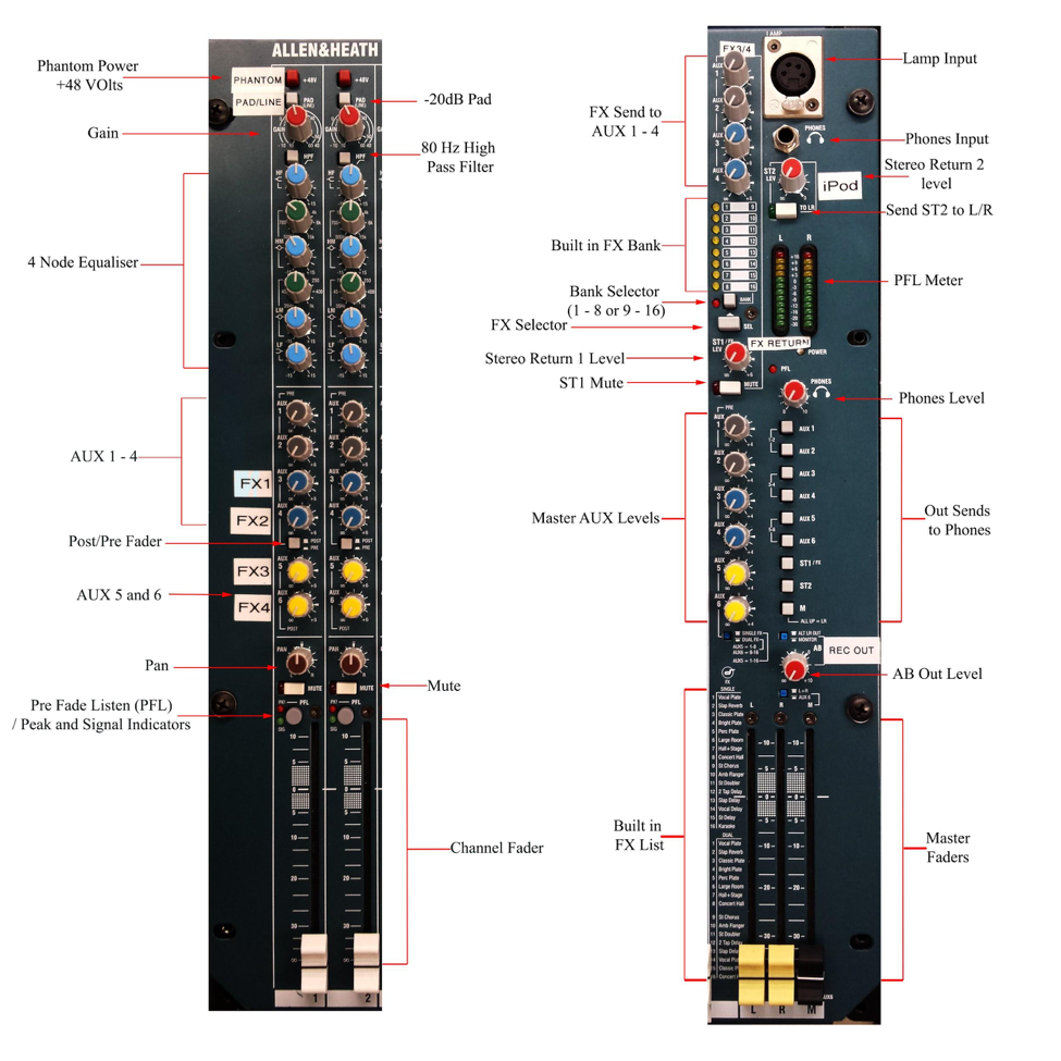 Figure 12: Labeled images of two input strips (left) and the master strip (right), on the MixWizard3
Master Channel Strip:
On the far right of the console, next to all of the input channels, is the master channel strip. At the top right corner you will see what looks like a XLR input, only with four pins instead of three. This input is actually for a gooseneck light if you are working in a dark space and need to see the board. The light can be found in the pullout drawer of the rig and has a small switch on the top of the bulb encasing which you can use to switch the light on and off. Directly below this light input you will find a quarter inch input for headphones (monitoring), and below this the master knob for Stereo Return 2 with a button labeled ’TO LR’ which sends whatever your return signal is from ST2 to your main mix. If you are wondering how stereo returns work, you can read section 8, which details an effects processor we have routed through ST1.
Internal Effects (FX):
On the left of these inputs and parameters (still at the top of the Master Channel Strip) are a set of four additional AUX knobs for AUX 1 through 4. These act as FX sends for the built in effects processor in the MixWizard, which means that if you are using one of these built in effects and want to send it to, say, AUX 1, you would use the AUX 1 knob up at the top of the master channel strip to do this. Do not confuse these AUX knobs with the master AUX knobs farther down the master channel strip. Below these AUX knobs you will see a list of banks, 1-8 and 9-16, below which is a small square button labeled ’bank’ with a red light and a rectangular button labeled ’sel’ for select. These banks correspond to the effects listed at the bottom of the master channel strip on the left of the master channel faders. Use the select button to browse through the effects until you reach the number corresponding to the effect you want. Use the small square button above it to switch to bank 9-16. When you press this button down the red light will come on indicating to you that you are in bank 9-16 rather than 1- 8.
These built in effects are routed through AUXes 5 and 6 (notice that the FX send AUX knobs I was talking about in the last paragraph only include 1-4. Again, Do not confuse these with the general AUX sends which I am referring to now), and the return signal comes through stereo return 1 (ST1) and into your master mix. If you look below your master AUX knobs on down the channel strip and just above your master faders, you will see three small recessed blue buttons with labels next to them. The one on the upper left allows you to switch between ’single FX’ and ’dual FX’ as labeled. When single FX is enabled the processor works as a single effects unit routed to AUX 5. We however typically leave the button in dual FX mode, which causes the effects processor to work as a dual effects unit, routed through AUX 5 and 6. In dual FX mode, when you select an effect in the bank, say number 3, the effect will be routed to AUX 5 and the corresponding effect in bank 9-16, namely 11 in this example will be routed to AUX 6. Make sure you are looking at the ’Dual FX’ list next to the master faders rather than the ’Single FX’ list when in this mode. To apply your chosen effect simply unmute ST1 and set it to unity and slowly turn up your input channel AUX 5 or 6 knobs while checking your mic corresponding to that input channel. You should hear your chosen effect coming through your mains. Note that you DO NOT need to have your master AUX 5 and 6 knobs turned up in order to use the built in effects processor. The master AUX 5 and 6 knobs only need to be used when you are using AUX 5 or 6 for the purpose of say a monitor, or some other general audio send.
Master Meter: Next to your effects banks you will find the master meter, which displays your pre-fade listen (PFL) signal when you have any of the PFL buttons on your input strips pushed down. This is a very useful tool for checking if you are getting signal to your mains before turning up your faders.
Headphones Control:
Below your master meter is your master headphones knob, which controls the volume going to your headphones (used for monitoring the mix). Below this knob is a column of small grey buttons corresponding to all of the possible outputs on your board, as you will see labeled. Selecting one or more of these will send the corresponding output signal to your headphones. When none of them are pushed down, the system defaults to the Left Right mix and sends this to your phones.
Master AUX Knobs:
Next to these buttons on their left are the master AUX knobs. When using any of your AUX outputs you must remember to turn the corresponding AUX master knob up, or else you will not get anything out of these outputs. For example, if you are trying to send signal from channel 1 to AUX output 1, first make sure that your output is cabled correctly and the speaker is working. Then turn your master AUX 1 knob up to unity. If the pre/post fade button is set to pre, then without turning up your channel 1 fader you can begin to turn up your AUX 1 knob on channel 1 while checking your mic plugged into channel 1. If your pre/post fade button is set to post, then you must turn up your channel fader (to the mains) first in order to get anything out to your monitor.
AB Out:
Below the master AUX knobs and the headphone send buttons you will find a knob labeled AB out, three small recessed blue buttons, and your three master faders: Left, Right, and M, in addition to the internal FX lists. The AB out is essentially an extra stereo left right output. The small recessed blue button above it selects the input source. When it is set to ’ALT LR OUT’ it picks off the signal coming out of your Left/Right Main output. When it is set to Monitor it picks off whatever signal is being sent to your headphones above. In our rig the AB out is fed to the input of the Tascam CDR 200 for recording purposes, therefore you should not need to change its source from ALT LR OUT. If you were at a gig in which there is a separate engineer running monitors, then you might use the AB out in Monitor mode to send the engineer whatever outputs he might want to be able to hear from your board. For our purposes however it is best to leave this output routed to the Tascam for recording purposes. It could also be used as a videographer feed, however as I am about to explain in the next paragraph we already have the M fader dedicated to this purpose.
Mono Out:
The small blue button below the AB out sets the source for the M (Mono) master fader on the far bottom right of the board. If it is set to L+R, then the M fader controls a summed Left Right Mono output, labeled as MONO OUT in the I/O panel at the back bottom of the rig (Figure 2). This is useful for external recording purposes, for example if a videographer arrives at an event and asks you for a feed from your board, you can give him the ’M’ out feed. If the button is set to AUX 6 then this fader acts as a master fader for AUX 6. We leave ours set to L+R.
5. The Rack
We can now move on to the hardware beneath the mixing console. Collectively each unit is screwed into the rack beneath the mix console, which holds them in an organized and easily accessible fashion, hence the name of this section. Starting from top to bottom we have:
- Furman PL-PRO C
- two DBX 266xs Compressors/Gates (four channels in total)
- Lexicon MX200 Effects Processor with 2 input channels
- PreSonus Studio Channel Preamp
- TASCAM SS-CDR200 CD Player/SD Recorder
- DBX DriveRack PA+ loudspeaker management system
- DBX 231s Graphic Equalizer
- two DBX 215 Graphic Equalizers (four channels in total)
- two Shure ULXP4 wireless microphone receivers
- QSC GX7 Power Amplifier
- metal pullout drawer
1. Furman PL-PRO C
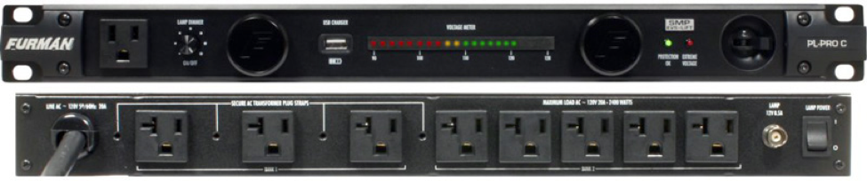 Figure 13: Furman PL-PRO C
This piece of hardware is simply a power conditioner which controls power sent to all hardware in the mobile rig. The switch on the far right labeled RACK POWER turns the entire rig on and off. The Pl-Pro also has two pullout lights. If you are working in a dark space and need to access any of the rack hardware, pull out these lights and press the knob to their left labeled ’Lamp Dimmer On/Off’ to turn them on. Adjust the dimness of the lights by twisting this knob. The PL-Pro has a voltmeter in the center, a USB power supply and Edison inputs on both the front and back for power to external devices such as laptops or phones.
2. DBX 266xs Compressor/Gate
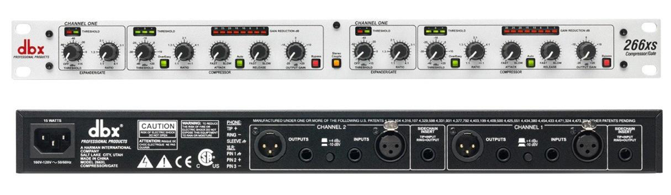 Figure 14: DBX 266xs Compressor/Gate
The DBX 266xs is a dual channel compressor/gate, which works as an inserted effect. Each channel is labeled as COMP 1, 2, 3 or 4, respectively. If you want to place a compressor/gate on a channel, go to the back of the MixWixard console. There should be a number of unplugged quarter inch cables resting in that area. Four of these should have corresponding COMP 1, 2, 3, or 4 labels on the connector piece. Pick the one you want and plug it into the ’insert’ input of the input channel of your choice. The ’insert’ inputs can be found just above the mic/line inputs on the back of the MixWizard.
You might also hear these inputs referred to as ’sends/returns,’ since these take the signal coming into your input channel, SEND it to wherever the other end of your insert cable goes, in our case one of our DBX compressors, and then the output of the compressor returns the processed signal back along the same cable and back into your input channel. For our particular mixing console, the inserts pick off the signal to send after the high-pass filter and before the EQ on the channel strip. Therefore, with regard to our compressors, when you insert one on a channel you can simply imagine a new set of knobs that control your compressor parameters between the high pass filter button and the channel EQ.
Going from left to right along the compressor, we first have the gate section of the first channel with threshold and ratio, along with a threshold meter in the upper left corner. We then have the compressor with your threshold knob, an ’Overeasy’ button (which controls the knee of your compressor [pushed down and lit up means a soft knee, pushed out and unlit means a hard knee]), ratio knob, attack knob, an auto attack/release button, release knob, output gain knob, and a bypass button. If you are trying to place a compressor on a stereo channel mix you can hit the small ’stereo couple’ button in between the two compressor channels. You might do this if you have two panned drum overheads, or if you are receiving a poor quality stereo playback recording. Each compressor also has a threshold and gain reduction (GR) meter. As mentioned before, there are four channels in total. Below is a link to the DBX site for this piece of hardware, where you can find documentation and a user manual.
http://dbxpro.com/en-US/products/266xs#documentation
3. Lexicon MX200 Effects Processor
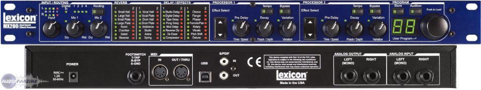 Figure 15: Lexicon MX200 Effects Processor
In addition to the built in effects from the MixWizard, the Lexicon offers two more channels of high quality effects. In the same way that the DBX compressors were routed via insert into an input channel, the Lexicon also works as an inserted signal processor, however the return signal takes a slightly different path on its way to the master outs. Instead of coming back along the insert cable, the output is sent to ST1, or Stereo Return 1 on the back of the MixWizard, in the same way that the built in effects are sent through this return on their way to your master mix. Going from left to right the Lexicon has an input gain knob, a mix 1 knob and a mix 2 knob. It then has four columns of listed effects with accompanying lights that indicate which effects are selected. Next to these lists are two sets of controls to select and modify the desired effect(s). These consist of the effect select buttons, a pre delay or time/speed knob, a decay or feedback/depth knob, a variation knob, and tempo and bypass buttons.
The labeled knobs vary in their purpose depending on which effect is selected, so a certain amount of trial and error is required when using the Lexicon. The technical manual for this device can be found in the pullout drawer at the bottom of the rig. The MX200 has two channels of effects, therefore in the back of the rig along with the four unplugged compressor cables you will also find two more unplugged quarter inch TRS cables labeled LEX 1 and LEX 2 respectively. To use the device plug one of these into the desired insert channel and make sure ST1 is turned up and unmuted. You can then select your effects using the ”Effects Select” buttons and set up your mix using the mix knobs on the far left of the Lexicon. Refer to the Lexicon Manual to determine how to use the three knobs in each ’Processor’ section of the device to adjust your chosen effect. If you use the ’LEX 1’ cable then you should be using the Mix 1 knob to control the mix volume, likewise with LEX 2 and Mix 2. For more details on how these parameters work please refer again to the manual, the link to which can be found below.
http://lexiconpro.com/en-US/products/mx200#documentation
4. Tascam SS-CDR200 CD Player/SD Recorder
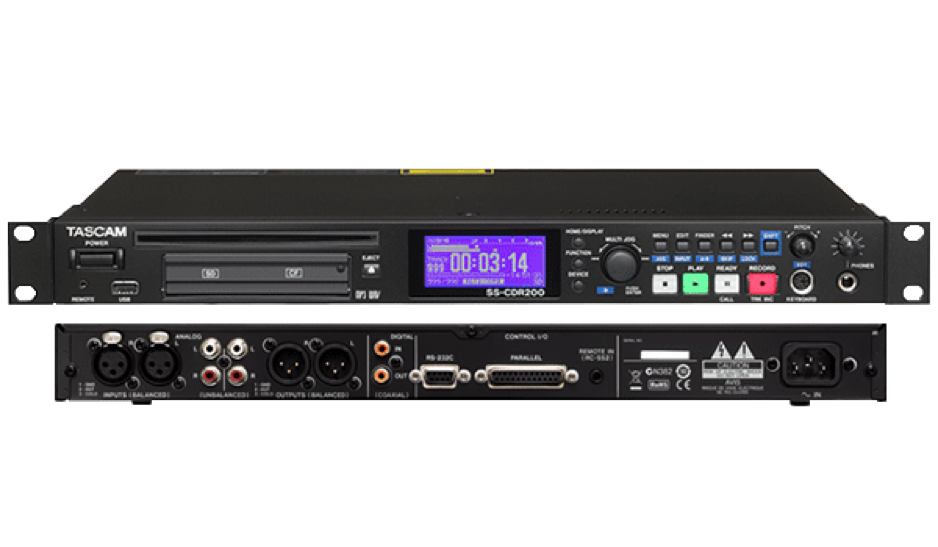 Figure 16: Tascam SS-CDR200 CD Player/SD Recorder
This part of the rack serves two main purposes: audio playback from a CD or SD card, and recording to an SD card. For specifics on how to set up recording to an SD card from this device or the handheld Tascam, please refer to our Tascam Recording guide. This discussion will be limited to audio playback. For many events you will be requested to provide house music. In most cases jazz is preferred, so we have provided a few jazz CDs in the pullout drawer of the mobile rig to choose from. To play the CD, first hit the Eject button next to the input side of the front of the Tascam. This will eject any CDs that were left inside the disc drive. Once you know the disc drive is empty insert your disc and hit the ’Device’ button directly to the right of the digital screen. This will pull up a list of the possible devices off of which you could play media files. Use the jog wheel (spin to move between selections, push down to select) to select ’CD’ and your disc should be automatically loaded and ready to go. Before playing the disc make sure the outputs of the Tascam are plugged in correctly by going to the back of the MixWizard console and looking at channels 15 and 16, which we use for the CD Player. A lot of times people may replace the CD player on these channels with an eighth inch to dual XLR for the purpose of playback from a phone or laptop. If this is the case then you will need to find the ’CD L OUT’ and ’CD R OUT’ quarter inch cables which should be laying around in the back with the other unplugged effect cables. Plug these into the LINE inputs of channels 15 and 16. Once this is done you can return to the front of the rig and press the play button on the Tascam to play the CD from the beginning. You can use the STOP, 21 PAUSE, and SKIP buttons to stop or pause the track and skip between songs. For details on how to record to an SD Card, please refer to the Tascam recording guide.
5. DBX DriveRack PA+ Loudspeaker Management System
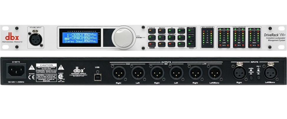 Figure 17: DBX DriveRack PA+
The DBX DriveRack PA+ is a very powerful piece of rack-mounted hardware. As the name suggests it manages your PA through the use of automatic system tuning EQs, feedback eliminators, and speaker leveling circuitry. If you look at the back of the DriveRack, you will see Right Left/Mono inputs that are patched from the L/R outs of the MixWizard and six line-level outputs labeled in pairs; a left and right output for High, Mid, and Low. In our rig you will also notice that all of these outputs except for the Low right output are being used. The Left/Mono output of the DriveRack goes directly to the ’SUB OUT’ in the I/O panel (see Figure 2). The Mid outputs go into the QS GX7 as I will explain shortly, and the High outputs go to the ’MAIN OUTS’, also in the I/O panel. You can effectively ignore the ’HIGH’ ’MID’ ’LOW’ labels on these outputs, as we are not using them as crossover outs for distinct speaker drivers like the names suggest. The DriveRack has crossovers and tunings already set up for each of these pairs and combinations of outputs.
Fortunately, most all of the uses of the DriveRack have already been set up and need not be touched, however the main feature of this machine which we put to use often is the automatic feedback eliminator. This is an extremely useful feature for working in smaller spaces like the Cafe or the Penthouse, especially when you run the risk of having a performer or speaker accidentally step in front of the PA with his or her microphone. The feedback eliminator detects feedback and automatically puts a sharp cut at that particular frequency, effectively eliminating the potential for feedback at that frequency. The DriveRack has up to six of these automatic filters.
To use the automatic feedback filters hit the button labeled ’FEEDBACK’ in the upper righthand corner of the button matrix to the right of the jog wheel. This will take you to a screen that looks something like this:
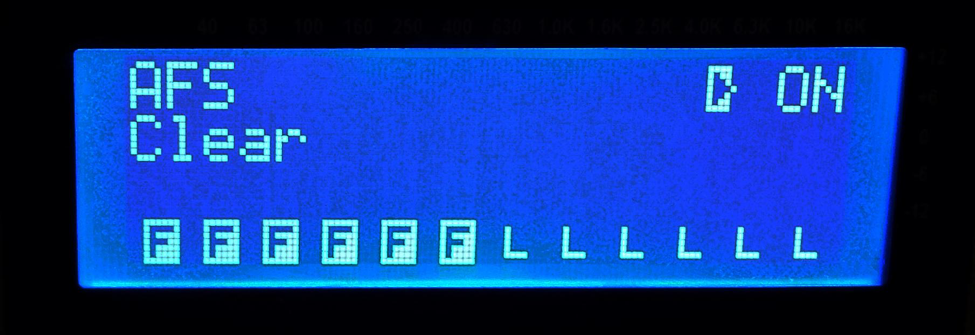 Figure 18: Example of the DBX DriveRack digital screen showing Feedback filters in use.
The six ’F’s on the lower left of the screen represent your six automatic feedback filters. If they are highlighted in white as in the picture above, this means that they are active and have already been placed at a particular frequency. To clear the filters and prepare them to detect new frequencies, push the jog wheel to the right of the screen directly down, this will switch your digital arrow indicator between the ’ON’ and ’Clear’ parameters. Once you are on the ’Clear’ parameter slowly spin the jog wheel clockwise to toggle from ’Live Filters’ to ’All Filters.’ Once you have ’All Filters’ selected push the jog wheel down again to move your indicator down and then slowly spin the wheel clockwise another notch. This should clear all of your filters and put them back in a sort of standby position, ready to detect and cut any feedback frequencies they detect. If you did this correctly the digital screen should now look like this:
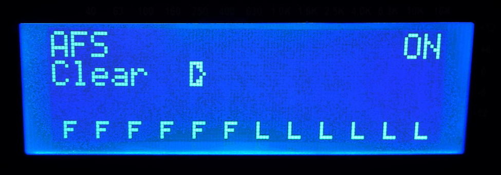 Figure 19: Example of the DBX DriveRack digital screen showing Feedback filters on standby.
ie: the ’F’ filters should no longer be highlighted in white. Typically at this point you want to announce to those in the room that you will be inducing feedback and give them a chance to leave or cover their ears, then take your mic, and slowly gain it up while talking into it until you start to hear feedback form. The device takes a second or two to recognize the feedback, however once it does you should hear it place the cut, eliminating the feedback and you should see one of the ’F’ filters go white on the digital screen. For more information on the details of this part of the rack simply refer to the DBX DriveRack PA+ website here to take a look at the user manual.
http://dbxpro.com/en-US/products/driverack-pa-plus#documentation
6. DBX 231s Graphic Equaliser
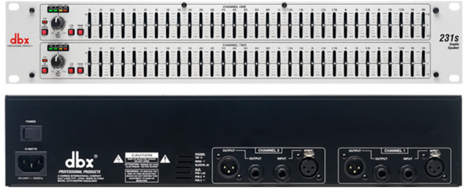 Figure 20: DBX 231s Graphic Equaliser
The 231s is a dual channel graphic EQ that works as an inserted effect just like the Lexicon and DBX compressors. You will find two more unplugged quarter inch TRS cables in the back of the rig labeled GEQ 1 and 2 respectively which you can insert into whatever channel you would like. The graphic EQ is typically used on the main LR output inserts in order to gain a master EQ on your master bus.
The 231s is split into two sections, one for each channel. Each one has a 20 - 20k Hz range graphic EQ with a gain knob, an input meter, a clip meter, a bypass button, a 50 Hz low cut switch, and a range switch that changes the range of the EQ from ± 6 to ± 12 dB. This effectively changes the sensitivity of the nodes/center frequencies on the EQ. You might want to use the ± 12 dB button when you are trying to manually eliminate a potential feedback frequency, since you would want a deeper cut for this purpose. You might use the ± 6 dB button when you are trying to fine tune your speakers, since for this purpose you shouldn’t in theory be cutting anything more than a few dB.
7. DBX 215 Graphic Equaliser
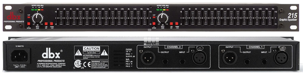 Figure 21: DBX 215 Graphic Equaliser
For our purposes the DBX 215 units are essentially identical to the 231s above, however they are routed differently. You will see that we have two channels of 215s. These have been dedicated to the purpose of monitor processing. There are two quarter inch cables on the back of the rack labeled MONS 1 and 2 that should be inserted in AUX outputs 1 and 2. The other ends of these two cables are plugged into the inputs on these top two GEQs. These are NOT to be used as inserts on input channel strips. The outputs of these two GEQs can be found in the I/O panel labeled as MONS 1 and 2 respectively. This means that when you send signal to AUX 1 or 2, that signal is now sent through a GEQ on its way to your monitor, giving you the option to ’ring out’ your monitors if necessary.
The term ’ring out’ monitors in the audio world refers to the process of removing any potential feedback via graphic equalizer from the monitors. You will need two people to do this. One person ’drives,’ or stands with a microphone on stage effectively trying to induce feedback in each monitor. When this person starts to hear feedback, he or she should roughly estimate the frequency of feedback (this process requires extensive experience and a fair amount of relative pitch. Unless you have a spectrum analyzer on your phone, you would typically just do this by ear) and communicate that frequency to the other person who should be standing at the front of house console (in this case the mobile rig) who would then cut that frequency in the GEQ.
8. Shure ULXP4 Wireless Microphone Receivers
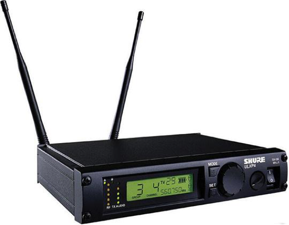 Figure 22: Shure ULXP4 Wireless Microphone Receivers
These are the receivers for the two wireless Beta 58s that can be found in the pullout drawer. Their channels are labeled ’W1’ and ’W2’ on the mix console. The receivers exist in order to receive the signal from the wireless microphone, convert it to a voltage and send it to your input channel. The signal from the microphone to the receiver is sent over radio frequency, indicated by the combination of letters and numbers you can see on the both the microphones and their corresponding receivers. The receivers, in addition to the microphones, have an internal volume parameter, given by the knob between the jog wheel and the power switch. This should not be touched and should be left at 100 percent (about five o’clock). The receivers also have a jog wheel used to change frequencies and settings, a ’Mode’ button and a ’Set’ button, in addition to the power switch.
These receivers have more settings and capabilities then you might imagine, but you don’t typically have to mess with anything on them. If anything, you may have to change the group and channel (frequency) on the microphone, also known as the transmitter. If you ever are having problems with a wireless microphone and notice that the group and channel on the microphone do not match up with the corresponding receiver, only make changes to the transmitter and NEVER to the receiver. That being said, ONLY begin trying to change the microphone frequency if you feel comfortable doing so. If this is where you find yourself, read on to find out how to change the microphone frequency to match its receiver.
The microphone frequency settings should always be locked when in regular use. That is, when you turn on the mic you should see a small lock icon on the right of the screen indicating that the mode and set buttons are locked and will not allow you change the group and channel of the transmitter. To unlock hold the set button and turn off the mic. Continuing to hold the set button, turn the mic back on. You should see the letters ’Fr UL’ for ’Frequency Unlocked’ appear first on the screen. Now use the mode button to switch between the ’Group’ and ’Channel’ of the transmitter and use the set button to get to a specific group and channel. When you have reached your desired group or channel, simply press the mode button to switch to the next section, or if you are already in channel mode, to return to the home screen. Your new group and channel should be showing up. If you have successfully changed your transmitter frequency in this way, please lock the microphone again by holding the ’set’ button, turning the mic off, and turning it back on, all the while continuing to hold the set button. You should now see the letters ’Fr L’ for Frequency Locked appear for a few seconds when the mic switches on.
9. QSC GX7 Loudspeaker Amplifier
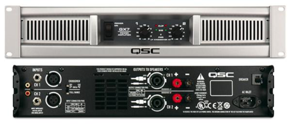 Figure 23: QSC GX7 Amplifier
The QSC GX7 Loudspeaker Amplifier is used to power our EV TX1122 loudspeakers. These speakers are ’passive’ which means they require an external power source and crossover, as opposed to ’active speakers’ like our JBL PRX612Ms, which are self-powered with a built in crossover. The QSC GX7 takes a split of the main output of the MixWizard (coming from the ’Mid’ outputs of the DriveRack as mentioned above) and amplifies it to speaker level, sending it out along with power through the PASSIVE OUTS on the I/O panel via Speakon NL2 cable. The two volume knobs on the face of the unit should both be set to 10, and the power button should never be touched, as it turns on with the rest of the equipment with the Furman.